Balancing Robot - Using PicBasic Pro
Most balancing robots have to use C or something that gives them floating point math for the gyro rate stuff. I use an External Floating Point unit for the math, assembly language interupts to control the servos, and PicBasic Pro to tie it all together.
I saw an article about Kalman filters, and threw this together in about 4 hours. Didn't like the way the KF worked, so I threw it out and wrote my own drift compensator. Works great!
|
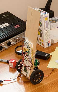 |
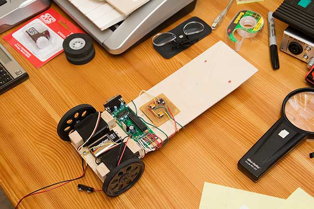
Kalman filters are used a lot in Nav and IMU systems, and I want to learn about them. When I saw this article about them in Nuts & Bolts magazine, I wanted to implement it. So I built this balancing bot using 1/8" birch, some continuous rotation servos, and just screwed my development boards right to the birch frame.
Took about 1 hour to build the frame, and 3 hrs to write the code and wire the parts. Works Great.
Here's a QuickTime Movie of the Robot Balancing.
Uses PIC16F876 mpu with PicBasicPro & asm, external Floating Point processor, and 5DOF IMU from Spark Fun. (2-Gyros, 3 Accelerometers)
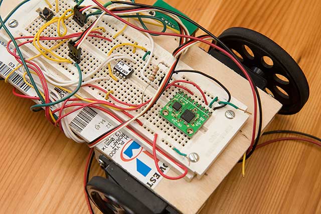
Here's the IMU - 5DOF and the uM FPU from Spark Fun.
Trouble is, the IMU chips wants 3.3v, and my MPU wants 5volts. What to do...
So I built a little add on board, with 2 pots (for PID trim control) and a 3.3volt power supply. It's also used as the voltage reference for the AD converters on the PIC chip, for more accurate readings from the IMU. This pic also shows the PIC dev board with PIC16F876 and Max232 / DB9 for RS232 terminal debugging.
The code required 3 sections: Read the Gyro & tilt sensor, Integrate the data, and drive the wheels.
The code runs on a PIC16F876A mpu, with a uM FPU chip for floating point and Spark Fun 5DOF IMU.
PicBasic Pro Source Code: BalancingRobot.pbp
Schematic: BalancingRobot.pdf
Back to Pete's Robo-Page