H-Bridge, ESC & Quad Encoders
To make any robo-go, you need to control the motors. Either using R/C servos, or an H-Bridge & Pulse-Width Modulated Speed Control.
To tell how fast or how far you're going, you need wheel encoders.
| Speed Controllers |
|
|
Speed controls cost a lot. I'm cheap and like to build things, so using the web, I learned how to build my own.
Here's how to control the speed of things, and how to measure how fast, or how far, you've gone.
DC Motors, H-Bridges, PWM and Duty Cycle = Electronic Speed Controller. (ESC)
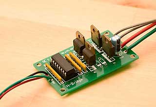
This H-Bridge Circuit is from a Chuck McManis design. He has written an excellent tutorial on H-Bridges.
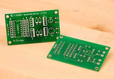
I liked the circuit so much, I drew it up and had some PCBs made. Download Gerbers here.
The code runs on a PIC16F873A, Arduino, or Atmel AVR chip running C.
PicBasic Pro Source Code: Speed_Control.pbp
AVR C Source Code w/PID feedback loops (.zip file):MotorControl.c
Arduino Source Code: HBridge.ino
| Quadrature Wheel Encoders |  |
Wheel Encoders are used to measure the number of times a wheel or axle or motor shaft have gone around, so you can derive either speed or distance traveled, or both. "Quad" encoders use two sensors and a special encoder disk to get twice the resolution, plus direction information, out of just two I/O pins. More on Rotary Encoders.
Other types of encoding systems:
Note: You can NOT use a regular dye based ink jet printer to print Encoder Wheels, the IR sensor sees the black dye as white paper. You can use a Lasor printer, or pigment based printer. Or print on ink-jet and have a Xerox copy made.
 |
|
|
|
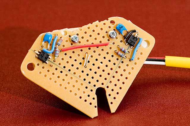
To make the sensors, I used the Hamamatsu Photoreflector IR sensor. They shine a beam of Infra-Red light with one dot, and sense it's reflection with the other dot. The Hamamatsu sensor is no longer available, but this looks like a similar device.
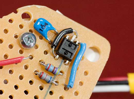
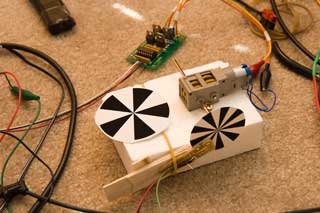
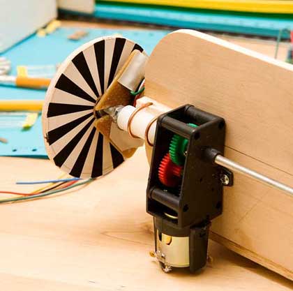
Here's the board I built with two detectors for a Quadrature Encoder System. The slotted hole fits over the drive shaft and is the center of rotation. Notice the two sensors are at exactly 90 degrees to each other, with respect to the drive shaft, so for any wheel with an odd number of segments per 180 degrees, one sensor will be on a transition while the other is centered within a segment. Check out the different wheel patterns above. (a 10 segment wheel will work, 5 per side, 18 segments works, 9 per side, 16 segments does not work, 8 per side, both sensors will see the transitions at the same time) I'm using a wheel with 30 segments. The Quad system will give me 60 "clicks" per rotation.
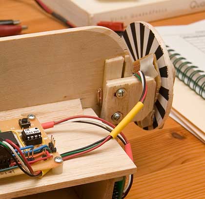
Here's the sensor board mounted on the Orb chassis. I used slotted holes to mount it so I could move it back and forth to adjust the distance to the encoder wheel. The sensors are fairly touchy and want to be about 3mm away from the target.
 |
 |
Quad Encoder Source Code
I found this wheel encoder code on the web and like it a lot more than the table based systems I also found.
(but now I can't find the authors name, to give him credit - I'll keep looking)
This code is run in response to a 1.25khz timing interupt, and runs in the background. It increments/decrements a foreground variable QuadCount that the main program reads, and clears, to track velocity and distance traveled.
QUAD_CHECK:
MOVF PORTB,W
MOVWF _QuadPins
RRF _QuadPins,F
MOVLW 3
ANDWF _QuadPins,F
MOVF _QuadPins,W
XORWF _QuadPrev,W
BTFSC STATUS,Z
GOTO ISR_DONE
SUBLW 3
BTFSC STATUS,Z
GOTO Quad_Error
BCF STATUS,C
RRF _QuadPrev,W
XORWF _QuadPins,W
MOVWF _QuadPrev
BTFSS _QuadPrev,0
GOTO Dec_Count
INCF _QuadCount,FQuad_Done:
MOVF _QuadPins,W
MOVWF _QuadPrev
GOTO ISR_DONEDec_Count:
DECF _QuadCount,F
GOTO Quad_DoneQuad_Error:
INCF _QuadError,F
GOTO Quad_Done
; Read Quad Sensor Pins - PortB Pins 1&2
; data in slots 0110
; Roll right -> 0011
; only want bottom 2 slots
; AND with 0011
; see if they're the same
; prev pins same as current - no change
; see if both pins changed
; shouldn't happen
; Clear carry bit
; Roll bits
; Check Direction bits...
; Dec Count -1
; Inc Count +1
; save new pin state
; done with interupt - exit
Here's some code I wrote in C for an AVR chip that handles decoding 2 "interrupt on change" sensor lines:
// Quad_read_pins()

// Called from the 2 Interrupt handlers when a pin changes state.

// Check for state change errors, then Inc/Dec Quad_Count if OK.

// Decode motion based on Standard Quadrature Encoder truth table:

//

//    prev crnt Direction

// -----------------------------------

//    00 -> 01   -1

//    01 -> 11   -1

//    11 -> 10   -1

//    10 -> 00   -1

//

//    00 -> 10   +1

//    10 -> 11   +1

//    11 -> 01   +1

//    01 -> 00   +1
void Quad_read_pins(void)

   {

   uint8_t crntPin1, crntPin2, thePins;


   thePins = PIND; // read port D pins 2 & 3

   crntPin1 = (thePins & 0x04) >> 2; // 0b 0100

   crntPin2 = (thePins & 0x08) >> 3; // 0b 1000


   if ((crntPin1 != prevPin1) || (crntPin2 != prevPin2)) // make sure something changed.

       { // error if both pins changed.

       if (!((crntPin1 != prevPin1) && (crntPin2 != prevPin2)))

           {

           if (crntPin1 == prevPin2)

               Quad_Count++;

           else

               Quad_Count-;

           }

       prevPin1 = crntPin1;

       prevPin2 = crntPin2;

       }

   }
Links to Complete Source Code (in Basic & Asm):